PIC UART CONTROL

UART stands for Universal Asynchronous Receiver / Transmitter. It is a serial communication interface which uses two lines for sending (TX) and receiving (RX) data. As its name indicates it is an asynchronous communication interface, which means it doesn’t need to send clock along with it as in synchronous communications.

UART stands for Universal Asynchronous Receiver / Transmitter. It is a serial communication interface which uses two lines for sending (TX) and receiving (RX) data. As its name indicates it is an asynchronous communication interface, which means it doesn’t need to send clock along with it as in synchronous communications. UART is the communication standard of our old computer’s RS-232 serial port. Most of the Microchip’s PIC Microcontrollers have built in USART Module. USART stands for Universal Synchronous Asynchronous Receiver Transmitter. It can be configured in the following Modes :
- UART – Asynchronous (Full Duplex)
- USRT Master – Synchronous (Half Duplex)
- USRT Slave – Synchronous (Half Duplex)
In this tutorial we are concentrating on sending and receiving data in the UART Mode using Hi-Tech C compiler. You may already know that Hi-Tech C has no built in functions for these, so we require some hardware knowledge for writing the code. I am going to explain it in deeply. If you don’t need deep knowledge in this, please skip to the coding section.
PIC 16F877A USART in Detail
USART Registers – PIC 16F877A
TXSTA – Transmit Status and Control Register
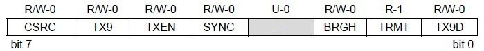
TXSTA – Transmit Status and Control Register
- Bit 7 CSRC : Clock Source Select Bit, this bit has no application in the Asynchronous mode operation of USART module. It is used to select master or slave mode in Synchronous mode operation.
- Bit 6 TX9 : When this bit is set it enables the 9 bit transmission otherwise 8 bit transmission is used. 9th bit in the 9 bit transmission mode is commonly used as parity bit.
- Bit 5 TXEN : Setting this bit enables the transmission. In the synchronous mode operation CREN and SREN bits of RCSTA register overrides this bit.
- Bit 4 SYNC : This is the USART Mode select bit. Setting this bit selects Synchronous mode while clearing this bit selects Asynchronous mode.
- Bit 3 Unimplemented : This bit is unimplemented and will read as 0.
- Bit 2 BRGH : This is the High Baud Rate Select bit for Asynchronous mode operation and is unused in Synchronous mode. Setting this bit selects High Speed and clearing this bit selects Low Speed baud rates. You will can see the baud rate calculation later in this article.
- Bit 1 TRMT : This is the Transmit Shift Register (TSR) status bit. This can be used to check whether the data written to transmit register is transmitted or not. When the TRS is empty this bit is set and when the TSR is full this bit will be 0.