We released a new parts editor in version 0.7.9 of Fritzing, so these tutorials are currently out of date. The instructions about how to create graphics outside of Fritzing are still correct, but the specifics of how you use Fritzing's parts editor have completely changed! For more info see this blog post.
Every Fritzing Part must have 3 different graphics for each of the 3 different views (Breadboard, Schematic and PCB), plus an icon for the parts bin. SVG, PNG and JPEG formats are supported (except for the part's pcb graphic which must be an SVG for the gerber files export to work well).
Using JPEG & PNG images is the easiest and fastest way to get things done, although zooming might pixelate your image. If you are interested in sharing your custom parts with the Fritzing community, we strongly recommend using a vector graphic editor to draw all part's graphics in SVG format.
You can use the open-source tool Inkscape (free and cross-platform), the commercial tool Adobe Illustrator (costly and Win/Mac only), or any other vector drawing tool that supports the SVG Tiny or Basic standards (see this list of tools).
Before you start creating your own graphics, check the existing graphics in the subfolders at Fritzing>parts>svg>core and Fritzing>parts>svg>contrib. Especially when you need to create a custom PCB footprint, the contrib folder can save you a lot of work.
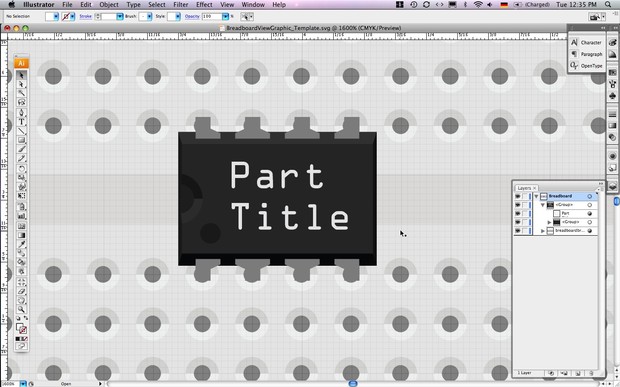
Let's start with the breadboard and schematic graphics. Use the
template files
or modify an existing part's graphics following these rules:
- Design according to Fritzing's graphic standards.
- When modifying an existing part, never rename its connector paths.
- Do not use any effects such as gradients and other bitmap effects.
- Use the part's datasheet and use a caliper so that you can get the correct external dimensions and reliable information about the part's specifications. You will also find the schematic symbol in the datasheet, which you can use for the schematic view graphic.
- A graphic for the PCB View should be grouped according to the different PCB layers. Open an existing footprint in Inkscape to understand how it is done.
Now make your SVG compatible with Fritzing:
- Delete all graphical artefacts like masks, meshes and styles.
- Delete all unnecessary layers (for example a breadboard image that you used as reference).
- Rearrange all graphical elements inside a single layer.
- Group all graphical elements and rename this group according to what it represents (“breadboard”, "schematic", "pcb" or "icon").
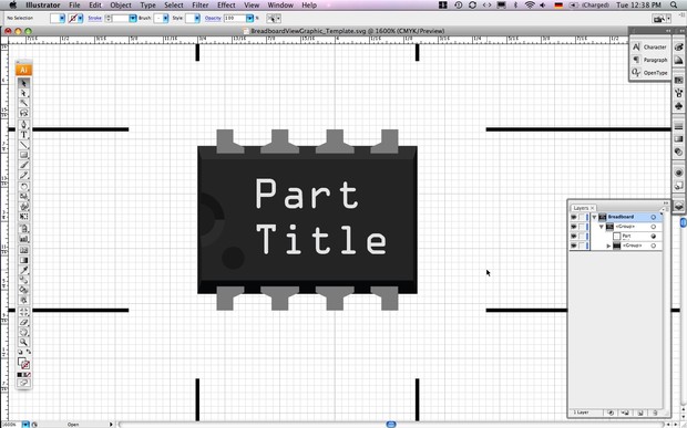
- Resize the art board to the external dimensions of the part:
Inkscape: select the group, then go to "File>Document Properties" and click on "Fit Page to Selection".
Illustrator: use the crop tool and option “Fit crop area to Artwork bounds".
Please Note: a bug in illustrator might cause the graphics to move from the crop area after saving. Close and open the file again, use the grid and drag (do not align!) the graphics to the upper left corner of the crop area, making sure all graphics are within. Save the file again, close and open it to check that the graphics are now placed correctly. - Save it in SVG format (without any program-specific add-ons):
Inkscape: Save your file as a "Plain SVG" (not as Inkscape SVG)!
Illustrator: Save your file as SVG with the SVG profile Tiny 1.2 or Basic 1.1.
CorelDraw: Export your file as SVG and in the styling options choose "presentation attributes".
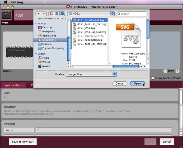
Once you're done, import the new breadboard and schematic graphics to the Part Editor by clicking the "image ..." link under each of the corresponding graphic fields. To import a new pcb graphic, navigate to the footprint svg. files at Fritzing>parts>svg>core>pcb. Find the footprint that fits your new part and click "open". In case you cannot find the correct footprint for your part, try modifing an existing footprint.
The parts bin icon represents your part in the Part Library. It can be created from a minimized version of the breadboard view graphic. This should be a 32x32px image and can be imported to Fritzing by clicking the "image ..." link under the small icon field at the upper left corner of the Parts Editor.
In the next step, we will define our part's specifications.