Fritzing's parts share the same graphic styles, colors and fonts. You should make sure to design your part according to the following standards. Please download our fonts and graphic templates before you start designing your part.
1. Breadboard View Graphics
Colors
|
Type
|
Name
|
Color
|
HEX
|
RGB
|
|
Legs
|
grey
|
8C8C8C
|
140 140 140
|
|
|
Contacts
|
copper/tinned
|
9A916C
|
154 145 108
|
|
|
Cables
|
blue cable
|
418DD9
|
65 141 217
|
|
|
blue cable (shadow)
|
1B5BB3
|
27 91 179
|
||
|
red cable
|
CC1414
|
204 20 20
|
||
|
red cable (shadow)
|
8C0000
|
140 0 0
|
||
|
black cable
|
404040
|
64 64 64
|
||
|
black cable (shadow)
|
000000
|
0 0 0
|
||
|
yellow cable
|
FFE24D
|
255 226 77
|
||
|
yellow cable (shadow)
|
E6AB00
|
230 171 0
|
||
|
green cable
|
47CC79
|
71 204 121
|
||
|
green cable (shadow)
|
00A63D
|
0 166 61
|
||
|
grey cable
|
999999
|
153 153 153
|
||
|
grey cable (shadow)
|
666666
|
102 102 102
|
||
|
white cable
|
FFFFFF
|
255 255 255
|
||
|
white cable (shadow)
|
999999
|
153 153 153
|
||
|
orange cable
|
FF7033
|
255 112 51
|
||
|
orange cable (shadow)
|
D95821
|
217 88 33
|
Fonts
Fritzing uses two types of fonts for parts in the Breadboard View:
For ICs: OCR A
For other parts: OCR A or Droid Sans
When using a different font, please converted the text into paths, otherwise it won't be compatible with Fritzing. To restate, if you are using Droid or OCRA it is not necessary to convert to paths. In general we recommend you use the standard fonts and keep text as text.
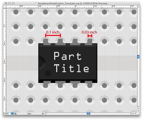
The standard font size is 5pt and font color 10% Black (RGB 230 230 230).
Grid & Dimensions
In order to fit into the breadboard, Fritzing parts must be designed with a fixed distance of 0.1 inch between the connector pins (legs).
Legs dimensions should be 0.03 inch wide and at least 0.03 long.
We recommend downloading and using our templates or the breadboard SVG as a reference while designing graphics for the Breadboard View.
2. Schematic View Graphics
Colors
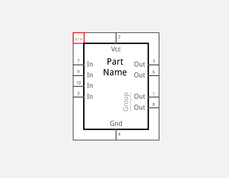
The part shape and title are in solid black (#000000 or rgb(0, 0, 0)).
Connector pins and their labels are dark grey (#555555 or rgb(85, 85, 85)).
If you group connectors, make the group label a lighter grey (#999999, rgb(153, 153, 153)).
Fonts
In the Schematics View, Droid Sans is used in different sizes according to the following hierarchy:
Part Name (4,25 points)
Pin Label (3,5 points)
Pin Group (3,5 points)
Pin Number (optional: 2,5 points)
Pin Character (3,5 points) - for example PWM
When using a different font, please converted the text into paths, otherwise it won't be compatible with Fritzing. To restate, if you are using Droid it is not necessary to convert to paths. In general we recommend you use the standard font and keep text as text--we are now beginning to manipulate <text> elements to keep them from mirroring and appearing upside-down when parts are flipped and rotated, and Fritzing looks specifically for <text> elements.
Grid & Dimensions
The fixed distance between the connector pins in the Schematic View is 0.1 inch.
Connectors dimensions should be 0,7 points (0,0097 inch) thick and 7,2 points (0,1 inch) long.
We recommend downloading and using our templates as a reference while designing graphics for the Schematic View.
3. PCB View Graphics
Colors
The PCB View uses the following colors:
| Type | Name | Color |
HEX
|
RGB |
|
Connector
|
copper |
F7BD13
|
247 189 19
|
|
| Silkscreen | black |
000000
|
0 0 0
|
Fritzing actually converts any other color to these ones on the fly. You will find many parts who still have a white silkscreen which is now converted automatically to black, to make it work with the new "white" PCB style that we introduced in release 0.8.6.
Fonts
The PCB footprint should not have any text, as it is dynamically created when working with Fritzing. If you'd still like to add some text, best to use the font "OCR A".
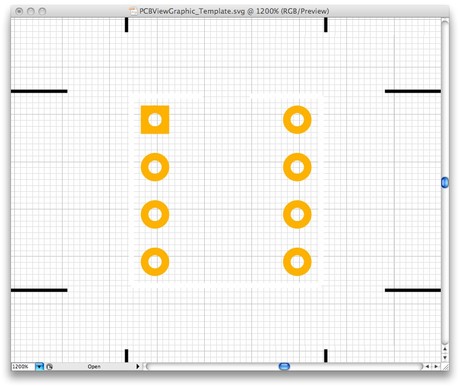
Dimensions
A Part's dimensions and distance between connector pins in the PCB View should be exactly as in the real world. This is extremely important for a successful pcb production. We highly recommend checking a part's dimensions in its datasheet.
Here are a couple of things to keep in mind:
- The stroke of a footprint should be at least 20mils (~0.5mm) thick, otherwise the connection might be ruined while drilling and soldering will be much harder.
- The hole itself should be at least 40mils (~1mm) thick, so you would actually need to create a circle which is at least 60mils (~1.5mm) wide in diameter, because half of the stroke is drawn inside the circle.
- If your part fits on the breadboard, the distance between the footprints should be 100mils (~2.5mm) long.
We also recommend downloading and using our templates as a reference while designing graphics for the PCB View.
4. File Naming Conventions
While it is possible to name files however you like, it helps to stick to a standard naming convention. These names should clearly describe the important attributes of a part and follow the order described here. By using standard names you make it easier for you and other users to find and reuse existing graphics. Although most description parameters are optional, it helps to provide as much detail as possible.
Breadboard and schematic images:
part#_description_package_pins_spacing_color_view.svg
For example an Atmel ATmega168 microcontroller in a narrow (300mil), 28 pin DIP package would have the following file name for the breadboard SVG file:
atmega168_microcontroller_DIP_28_300mil_breadboard.svg
PCB footprint SVGs follow a slightly different convention:
package_pins_spacing_pcb.svg
A PCB footprint SVG should only describe the industry standard "package" and not be tied to a specific part, unless the part has a unique specific footprint. In the case of our ATmega168, it uses an industry standard 28 pin narrow (300mil) DIP package, so the SVG file would be named as follows:
DIP_28_300mil_pcb.svg
Note: Many industry standard footprint graphics are already inside fritzing. It is usually best to check and make sure someone hasn't already created the PCB footprint SVG that you need. This saves you time and makes parts more consistent.
5. Graphics Templates for Download
Find all basic templates and related fonts for all views on the template download page.