ATtiny44 programmer board

Programming an ATyiny using a Nano as a Programmer


A simple board to program a ATtiny44 using an Arduino Nano as a programmer. Works also for other ATtinyx4 MCUs.
HOW TO
You need an Arduino Nano, a 14 DIP socket, two strips of 15 female header connectors each, a 5x7cm prototype PCB board, one LED, one 100 Ohm or higher resistor (depending on LED characteristics), a PC with the arduino IDE (version 1.6 or higher, not the one shipped with Ubuntu 16.04).
- Using the Nano usb socket, upload on the "ArduinoISP" sketch, as found in the Examples bundled with the Arduino IDE.
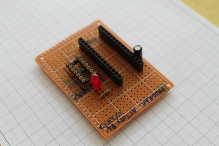
- Build the board following the Fritzing design.
 After assembling and soldering the board, plug the Arduino Nano you programmed in the previous step in the two female pin strips as shown in figure.
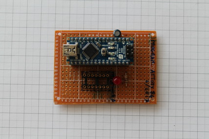
- Follow one of the many guides that teach how to install in the Arduino IDE the support for the ATtiny family.
- Insert the ATtiny44 you want to flash in the 14 pins DIP socket, with the notch on the LED side.
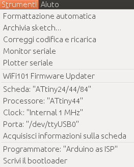
- Connect the Arduino to the PC USB socket, configure the IDE to upload to an ATtiny44 using the "Arduino as ISP" mode, and use the upload button on the IDE to flash your ATtiny with your sketch.
Testing
After assembling the board, with the Nano in place, connect the Nano with your PC an check with a tester that the GND and Vcc pins on the DIP socket receive the correct power.
There is a LED on board: to test your board and your chip, upload the test_attiny.ino sketch linked to this page, and check if the LED starts flashing when the uploading terminates.